


WHITE RODGERS THREE WIRE ZONE VALVES
Many a good man has been confused by the White Rodgers three-wire zone valve. All of them have model numbers that begin with 1311-10(2)(3)(4) 102 is ¾”, 103 is 1 inch, 104 is 1-1/4”. If the first digits are, 1361 it is a valve with two-wire control and we are not discussing it in this article.
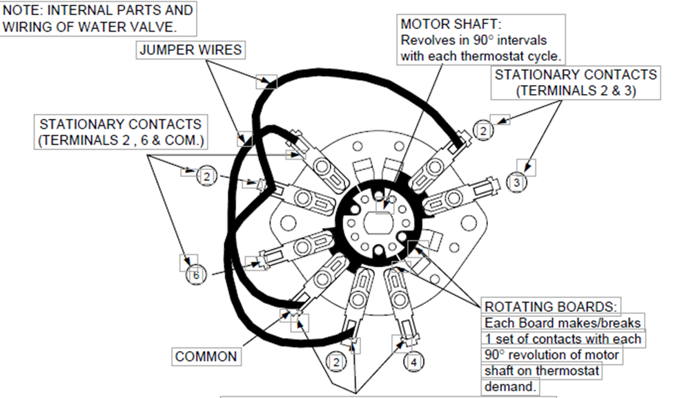
The 3-wire valve refers to three wire control these valves have five wires or maybe six if the end switch is used. Terminal one (1) is the transformer common. Terminal two (2) is the transformer HOT. Terminal three (3) is the end switch output. Terminal four (4) powers the valve open. Terminal five (5) is internally connected to terminal two (2) and is the 24v power to R on the thermostat. Terminal six (6) powers the valve closed. When the valve is open terminal three (3) connects to terminal two (2). Terminals one (1) and three (3) can power an auxiliary load like a relay. Multiple valves can have their end switches wired together. For that, it is best to have the installation instructions in hand.
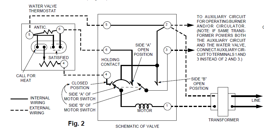
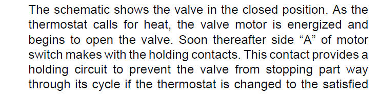
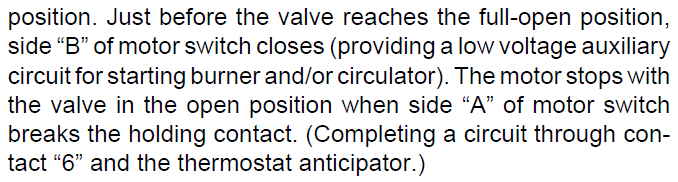
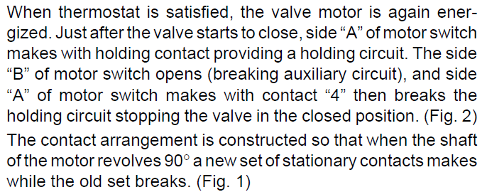
Having said that, now we need a thermostat. White Rodgers or Emerson has a few models with a terminal 6. Honeywell has a few that are suitable for series 20 wiring. If we deploy a RIBU1C relay any thermostat can do the job.
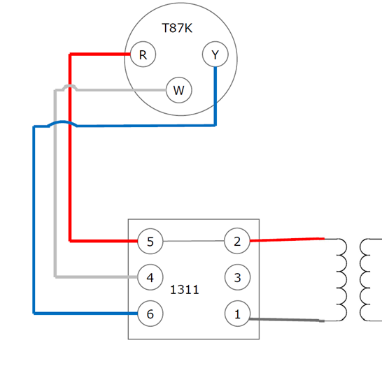
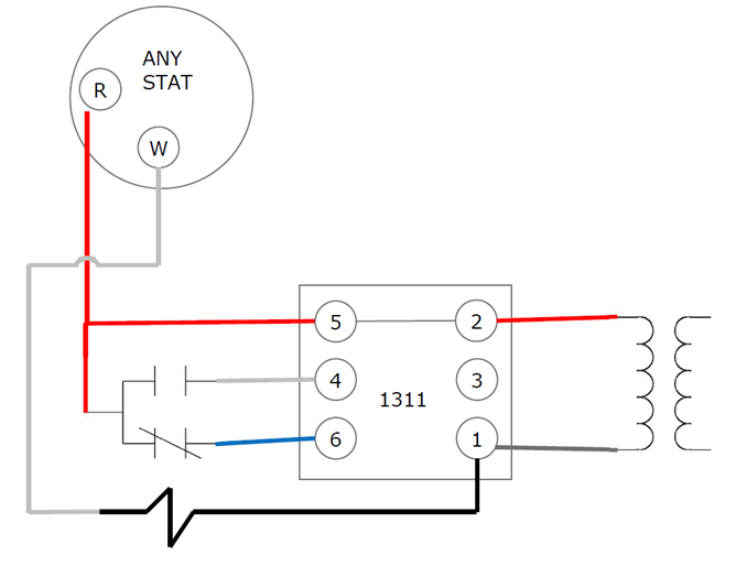
Here are a few wiring diagrams also for 3 wire zone valves:
Dallas Strong
Johnstone Supply
Key Takeaways: White Rodgers Three-Wire Zone Valves
✅ Identifying the Valve Type:
-
White Rodgers 3-wire zone valves have model numbers starting with 1311-10(2)(3)(4).
-
102 = ¾” valve
-
103 = 1” valve
-
104 = 1¼” valve
-
-
Valves starting with 1361 are 2-wire control valves and are not covered in this article.
✅ Wire Functions:
-
Terminal 1 = Transformer common
-
Terminal 2 = Transformer HOT
-
Terminal 3 = End switch output (connects to Terminal 2 when the valve is open)
-
Terminal 4 = Powers the valve open
-
Terminal 5 = Internally connected to Terminal 2; provides 24V power to R on the thermostat
-
Terminal 6 = Powers the valve closed
✅ End Switch Usage:
-
Terminal 3 can power an auxiliary load (e.g., relay).
-
Multiple valves can have their end switches wired together — installation instructions are recommended for this setup.
✅ Thermostat Compatibility:
-
White Rodgers/Emerson offers thermostats with a Terminal 6 for direct compatibility.
-
Honeywell thermostats suitable for Series 20 wiring are also an option.
-
For added flexibility, a RIBU1C relay allows any thermostat to control the system.
✅ Additional Resources:
-
Wiring diagrams for:
-
3-wire zone valve with a T87K thermostat
-
3-wire zone valve with any thermostat
-
By understanding these key points, technicians can confidently wire and troubleshoot White Rodgers 3-wire zone valves for reliable heating system control.
In Field Diagnostic TEST:
-
Kill power and verify deadCut 24V power to the zone valve circuit (transformer secondary or the fused disconnect feeding it). Confirm 0V at terminals 1-2 with your meter before touching anything inside the terminal cover.
- 2
Check valve motor power (terminals 1 & 2)Restore power. With the thermostat satisfied, you should read 24VAC between terminals 1 and 2 (the R/hot leg). If you don't, the fault is upstream of the valve, not the end switch.
- 3
Baseline the end switch at restWith the valve closed and idle, set your meter to continuity/ohms across terminals 2 and 3 (or 1 and 3 if that's how it's wired per the IOM note). It should read open (no continuity) — Side B of the motor switch is open when the valve is closed.
- 4
Force the valve open and watch the switch makeWith power on, jumper terminals 4 to 5 to drive the motor open (bypassing the thermostat). Leave your meter on 2-3 continuity. You should hear/see the motor run for most of the ~45 second stroke, then just before full-open, the switch should snap to continuity (closed). If it stays open through a full stroke, Side B's contacts are bad or the motor isn't reaching full travel.
- 5
Confirm switch action under loadIf continuity checks out, switch your meter to VAC and read across 2-3 with the aux circuit's transformer connected (or read voltage at the circulator relay coil terminals it feeds). You should see the relay's rated voltage appear right as the valve reaches open. A switch that shows continuity on an ohmmeter but won't pass voltage/current under real load usually means pitted or carbon-fouled contacts — meter continuity can lie under no-load conditions.
- 6
Force the valve closed and confirm the switch drops outJumper 5 to 6 to drive the valve closed. Watch that the end switch opens back up (loses continuity/voltage) shortly after the valve starts moving off full-open — it shouldn't stay closed through the whole closing stroke.
- 7
Remove jumpers and restore thermostat wiringPull the test jumpers, kill power again, and reconnect the thermostat leads to their proper terminals. Cycle the actual thermostat once to confirm the circulator/burner call comes in and drops out at the right points in the stroke.
The key diagnostic gotcha is step 5 — a lot of "bad end switch" calls are actually contacts that ohm out fine on a meter (which pushes negligible current) but won't carry the actual relay coil load once they're pitted or carbon-fouled. If you jumper it open and the switch continuities fine but the circulator relay still doesn't pull in, check voltage under real load before condemning the valve head.

